|
|
|
||

| |||
| Kepler Calibration | |||
|
PIXEL RESPONSE FUNCTION
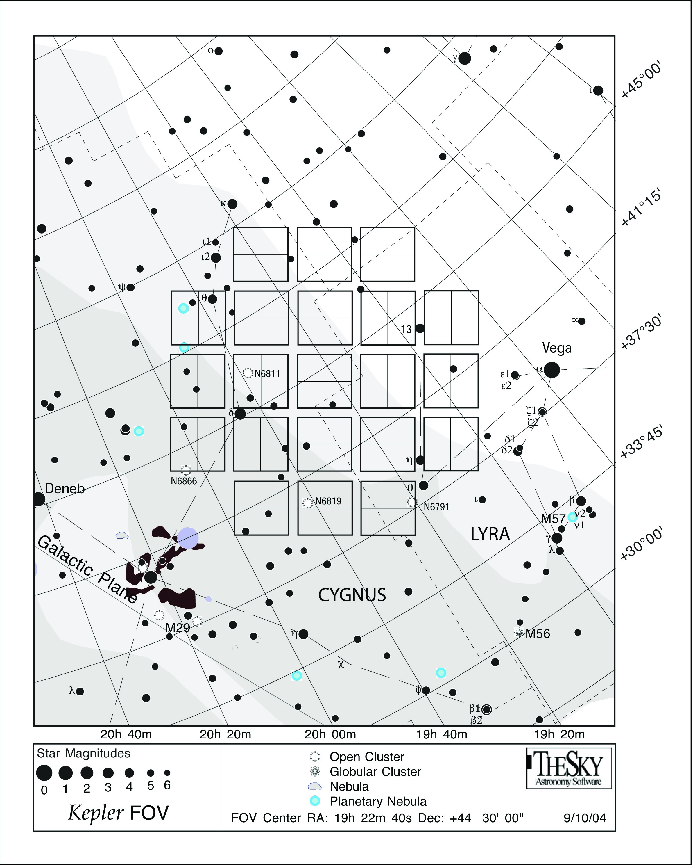
Image scale: 3.98
arcseconds per pixel DEFINITION Kepler was designed as a high precision photometer, not as an imaging experiment. The design requirements emphasize photometric stability and minimizing noise sources, in order to detect the small dips in observed flux produced by planet transits. Users should recognize that the optimum focal plane geometry for flux collection will not in principle provide the most compact point spread function, as is usually desired for imaging experiments. In particular, Kepler's pixel size precludes the type of high-resolution imagery obtained in the optical with Hubble, but is similar to other space-based multiwavelength imagers, e.g., GALEX. Kepler "images" will appear pixelated; modeling the PSF, if desired by the user, will require substantial effort. The Kepler point spread function varies considerably
across the focal plane, due primarily to the Schmidt optics, which provide a large FOV
approximately 16° in diameter. The Project quantifies the total response of the
instrument to incident light in terms of its pixel response function,
which represents the observed appearance of point sources. The PRF is a
combination of the optical design, focus setting, CCD detector mechanical and electronic
properties, and the temporal sequence of spacecraft pointing stability during an observation.
Not only does the PRF depend on location within the the focal plane, as defined by
a source's CCD channel, row and column location, but also depends on the intrapixel
location of the source centroid (peak incident light). Note that this definition is
somewhat different from the more common usage. A detailed summary of the characteristics
and modeling of the PRF is provided by
Bryson, etal;
(2010), the reader is strongly encouraged to review this paper, especially if the shape
of the PSF is important to your science.
Distribution on the Focal Plane Concentrating light in the brightest pixel will degrade the resulting photometry by increasing sensitivity to image motion, and constrain the ability to determine image centroids. Conversely, a too-broad PRF will include additional background flux and noise, reducing the signal-to-noise ratio of the source. Therefore, the optimal pixel response function for Kepler science operations was carefully designed to maximize photometric stability. The Project uses these metrics to quantify the PRF: the brightest pixel flux fraction (BPFF) and the 95% encircled energy diameter (EE95), evaluated for the spectrum of a G2V star. Level 1 requirements are: BPFF should be < 60%; the EE95 is required to be < 7.0 pixels. During the commissioning period, the focus was adjusted, and the resulting PRFs measured, using a large set of test stars. Images from this analysis, selected to have the stellar centroid closest to a pixel center are shown below in the Y+ Z+ focal plane array coordinate system. These images and the 95% encircled energy diameters are meant to give the observer a qualitative idea of how the PRF varies across the focal plane. |
 |
|
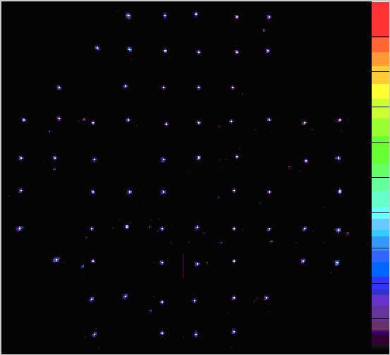
Examples of scaled pixel-centered pixel response functions based on commissioning data. The color bar indicates the square-root scaled value. PRFs are calculated near the center of the an output channel at row 535.0, column 550.0. Left: mod.out 9.2 (channel 26), smallest EE95. Middle: mod.out 13.2 (channel 42), median EE95. Right: mod.out 10.4 (channel 32), largest EE95. |
|
|
Pixel-centered images across the focal plane after focus adjustment during commissioning. Each source is normalized to the brightest pixel in the target aperture, rotated and translated to the common focal plane coordinate system, and linearly scaled to the color bar. Black lines along the color bar represent 10% intervals. (Some channels did not have satisfactory targets). The encircled energy targets are magnified by 50x compared to the spacing between them in this image. (Adapted from the Kepler Instrument Handbook) |
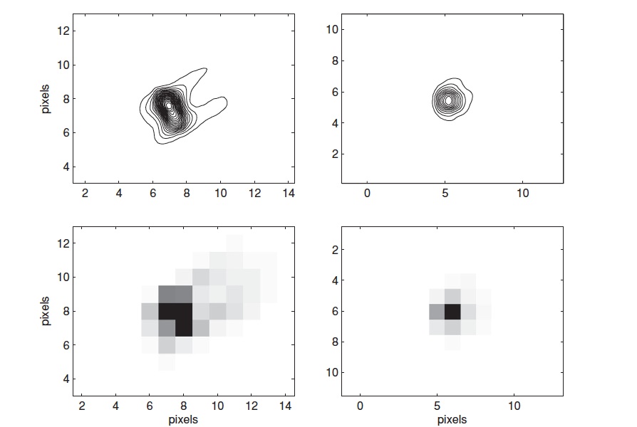
Expanded representation of the PRF at two locations in the focal plane. On the left: a PRF from near the edge; on the right: a PRF near the center. The pixelated image is shown below and a contoured version above. (Adapted from Bryson, etal). |
|
Vignetting As seen in the figures above, vignetting affects the PRF at
increasing distance from the center of the FOV, a consequence of the Schmidt optical
design and large FOV. Somewhat less than half of the active FOV is unvignetted, and
another ~30% is affected, but considered usable. Vignetting is negligible within
4.6° of the center, and increases to ~11% at the edge of the FOV at 6.94 degrees
off-axis. The area of sky which is vignetted < 11% is 151.2 square degrees, and the
sky area imaged onto active pixels with < 11% vignetting is 101 square degrees since
there are gaps between modules, a gap between the two CCDs on each module, and inactive
areas on each CCD. Further details are found in the
Kepler
Instrument Handbook, and the paper referenced at the top.
Guest Observer Considerations Astronomers frequently use knowledge of the PSF to derive photometry of their sources. Essentially there are three general methods for source photometry: 1) annular aperture photometry (with or without aperture corrections), 2) fitting the PSF to a mathematical form, e.g., Gaussian-fitting, and, 3) empirical PSF-fitting. The latter is often used in crowded fields or where the PSF lacks symmetry (as with many of the Kepler sources). Some considerations for Guest Observers:
|
|
|
![]()
Questions concerning Kepler's science opportunities and open programs, public archive or community tools? Contact us via the email address.